-
Project: E-ink frameI've made Raspberry Pi powered e-ink photo frame to display my schedule, to-do list and other information. There's 3D printing, woodwork, software, and some horrible Java.
Making things out of wood
Attaching bits to the frame
Frame software
Experience and re-printing
Final assembly
Planning the e-ink photo frame
I am not terribly organised and frequently discover I’m supposed to be in a meeting when either my phone starts beeping and flashing or - if I’ve left that somewhere - a friendly soul PMs me to ask where I am. I wanted to build an actual thing and thought I’d try and solve this problem at the same time.
I quickly thought of building something with a screen that can sit on my desk and display upcoming events. I had a Raspberry Pi sitting about and was confident I could figure out the code, I just needed a screen and something to hold it all together.
There are plenty of LCD screens available that would integrate easily with the Pi. There are even touch screens. My desk already holds two gargantuan monitors and I feared another backlit screen might make my eyes upset.
I settled on using e-ink: I don’t need back-lighting or colour, and I only want to display static content. If I could build this well, I could have something that didn’t look like a device at all.
The proper e-ink developer kits start around $1000. I looked into jail-breaking my Kindle and easing it out of the casing but my device is the Alcatraz of Kindles and its generation has yet to be broken out. I briefly fell in love with the giant Kindle DX, with a 9.7” display, but these were expensive to acquire and I’d probably have felt bad tearing it apart.
I eventually stumbled upon a company called Pervasive Displays, they were mentioned in a forum post about a tiny screen someone had included in a project. After further digging, I found a 7.4” 1-bit screen that I could get hold of for about $150.
Once it completed its journey from the US, I encountered my first problem almost immediately. I had to connect the screen to the driver board, with a thin ribbon cable, into a connector I had never seen before. After jabbing at it for nearly a whole afternoon, I discovered it was hinged and clamped the cable in place.
It would have been possible to communicate directly with the screen but I feared that may have been a leap too far for me, instead, I purchased an additional board (the USB2TCM Interface) which allows the screen to mount as a USB drive. In this case, a single file, in its strange proprietary format (we’ll get into that later), would be sent to the screen. I tested this with an octocat:
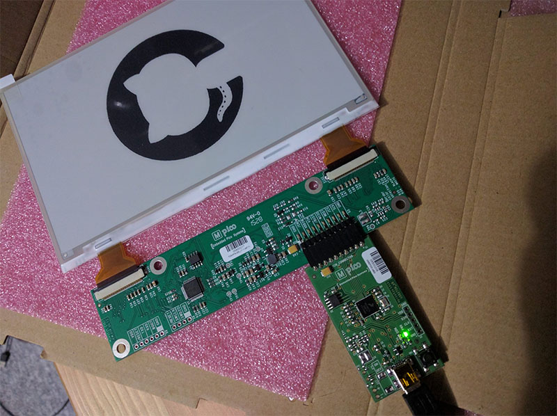
It looked great! The screen is only 1-bit. This means black or white, no shades of grey like you see on a Kindle; the edges of the circle are quite jagged - anti-aliasing isn’t a possibility. When I come to write the software for this, I’ll need to use fonts that work well in this colour depth.
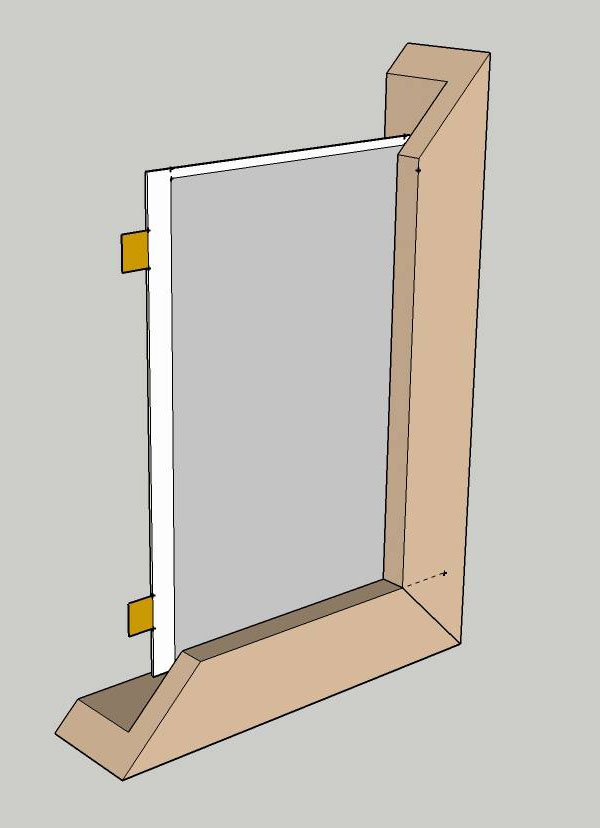
I decided that the ideal way to display this would be in a picture frame. I phoned around some local art shops and found one that sells lengths of moulding, after buying a piece and measuring it, I started creating the frame in Sketch Up:
In the next post, I’ll talk about how that went.
Making things out of wood
Continuing my project to build an e-ink photo frame calendar, my next step was to build the frame. This was comprised of two disasters and a compromise. I’m not very good at wood.
Disaster 1: DIY
I learnt how frame mouldings work and found a local art shop that would sell me a length. I built it in SketchUp and measured the model so I could be confident about the measurements. I then bought myself a mitre box so I could cut some beautiful 45° angles.
I have always struggled to saw straight but I thought the mitre box would be the solution to this. Surely it’s impossible to do anything but saw straight with a mitre box? It turns out, if you’re really bad at sawing things, it’s possible to saw through a mitre box. Once I had sawed new directions into all four 45° slots, I decided to power through and sand away the mistakes.
This almost worked. I had to do a lot of sanding but I eventually got the four pieces to fit together and look okay from the front. Unfortunately, I had done so much sanding that I lost a good few centimetres of screen aperture. This frame went into the box of offcuts so I could forget it existed.
Disaster 2: Communication breakdown
I went back to the art shop asked the same framer to build me a frame. I think he knew.
I was using the box frame moulding backwards; with the foot of the ‘L’ shape facing the viewer to cover the circuitry and outside-edge of the screen. Box frames are designed to be used the other way, so the item sits nicely in the frame. I forgot about that and when I asked for an aperture to fit the 7.4” screen, what I had unintentionally ordered was a box frame that the screen would sit in. When I went to collect the frame, the aperture was 4 inches long and 1.5 inches wide:
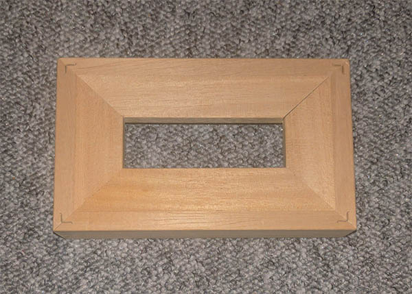
It’s okay to laugh.
I’m not particularly brave in these situations so I told him it was perfect, paid, and put it in the box with the other frame.
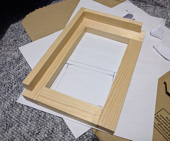
Compromise: 90° angles are less horrible
With talking to people and cutting angles abandoned, I decided to compromise and make it with straight cuts. I bought a better saw and set to work redesigning:
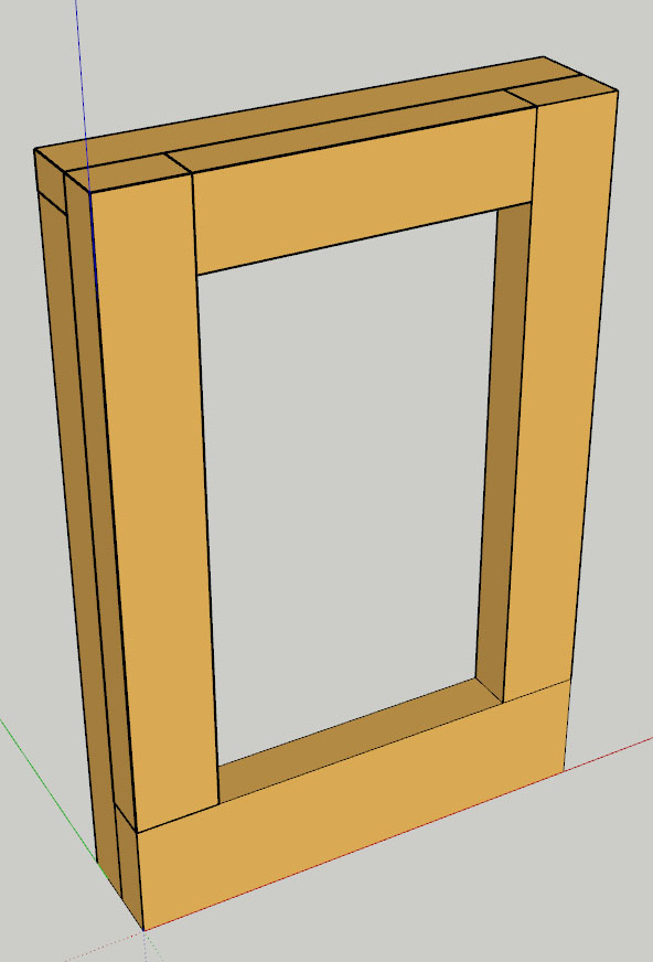
The left, top and right segments are 25mm wide while the bottom segment is 36mm wide. I prefer it looking slightly bottom-heavy and it will allow me to install a button if I ever want to make it more interactive.
To give some cover to the components, and to simulate the ‘L’ shape of the moulding I was trying to use, I attached more pieces to the back. These overlapped the joins on the front for (perhaps!) a bit more strength. I used some wood glue and clamps to get the front together.
The back was just glued up and pressed for a bit, the entire thing is lovely and strong. I might not trust it hanging on a wall, but with it sitting on my desk, I don’t think I’m going to have a problem.
Next up, attaching bits.
Attaching bits to the frame
Continuing my e-ink photo frame project, I now had a wooden frame. And two other frames I didn’t want to think about. Next up, I needed a way to attach everything together.
My initial plan was to use hardboard. It was from the back of a photo frame so seemed appropriate. I measured out what I’d need to cut in SketchUp:
(I had so much fun needlessly modelling small details on this project).
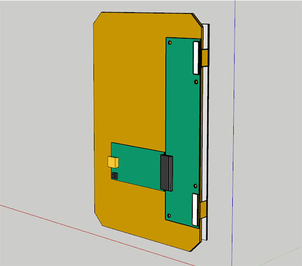
The hardboard, whilst strong, was ugly as all fuck and frayed when cut. I considered wood but the chances of me cutting it accurately were close to nil. I decided to treat myself and have my first foray into 3D printing - I already had everything measured precisely in SketchUp.
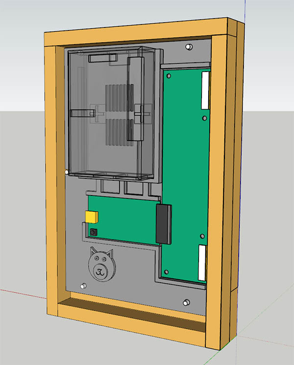
The grey bit is the model to be printed. The translucent shape on the top left is the case I had bought for my Raspberry Pi. I added 5mm raised walls around the e-ink board, the adaptor, and the Pi. Those strengthening-tubes you see between the Pi and the adaptor? I thought they looked nice. Maybe they make it stronger too? I also added a cat face because I am 9.
To attach the 3D printed back-piece, I sunk and epoxied bolts to the frame and used 3D magic to make opposing holes in the board. The board can then be secured with nuts. This is a bit backwards but it works; I’ve since discovered, and used, lovely “insert nuts” but I didn’t know what they were called at the time.
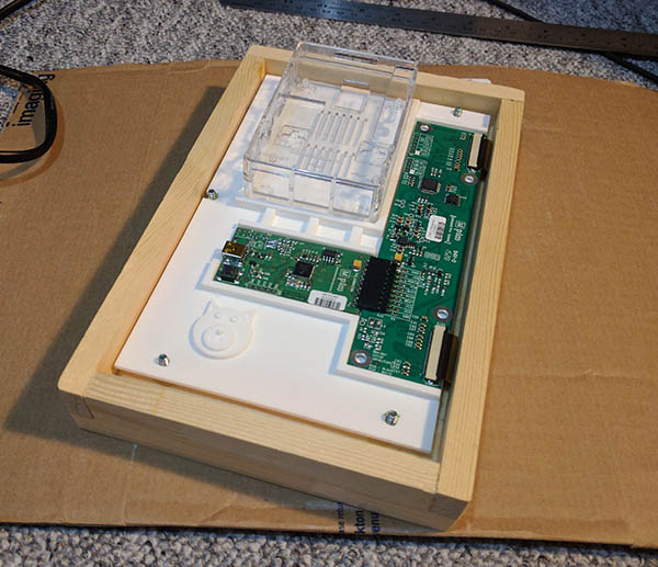
I had the board printed at 3DPRINTUK. It arrived quickly and is wonderful, they use a fancy laser based printing technique and the finished object looks perfect. It took a lot of self-control to not immediately spend all my money on printing more things; holding something you designed on your computer is a cool feeling.
I needed to file the little wall next to the Pi but everything else fitted fantastically:
Next up, I need to make it all work.
Frame software
I had a frame, a box of other frames I didn’t want to talk about, some circuit boards, and a piece of expensive plastic to hold it all together. My next task was to make it all work.
It would have been possible to use the Pi’s IO pins to communicate directly with the screen but I was not confident I’d get that working. Instead, I ordered a USB interface (USB2TCM) sold by the manufacturer. This mounts as a USB flash drive and allows you to transfer a single file which the interface reads and communicates to the screen.
Raspbian is a Pi-friendly version of Debian. I’ve installed Apache, so I can have some user-facing settings and an easier time debugging, and PHP 7, which this will be written in. So I can work on this locally, quickly deploy it to the frame, and eventually share the code with others, I’ve built a simple settings page that allows the user to add calendars and API tokens. This also allows me to toggle the environment; the “demo” environment halts execution after the image is built and displays it in the browser rather than trying to send it to the frame.
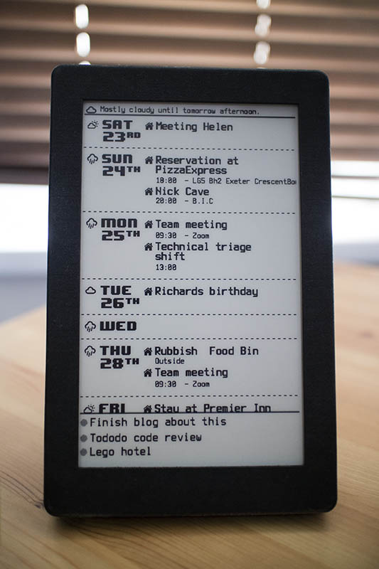
The task.php script gathers all the necessary information and draws a PNG using PHP’s graphics libraries. I’m using the private .ics address from Google Calendar. This gives me a file I can parse for each calendar but causes a few problems; the output is very.. raw. I’ve had to write my own function to recreate repeating events from their patterns (and modify individual occurrences as they are changed or cancelled). This is working most of the time.
The script also calls upon Darksky’s API to collect some weather information (what would a Raspberry Pi display project be without weather?). It also has a to-do list powered by a tiny API that allows me to update it remotely via a public-facing home server. Finally, you can also send the API little 32x32 pixel doodles that display in a repeating pattern at the bottom for 24 hours.
The biggest challenge in this project, other than talking to framers and cutting straight lines, was Pervasive Displays’ EPD format. The documentation contains a single snippet of Java for converting a bitmap into this format. Each screen they offer has a different format, and some - such as my 7” screen - are confusingly interlaced with each byte representing two parts of the image. I tried to recreate this snippet in PHP but had trouble using PHP to write binary data. It’s not something I had touched before and I couldn’t keep my nice stream of 1s and 0s in the right format.
I got so close at one point that I was sending images to the frame to try and perfect what each bit represented. These are meant to be triangles:
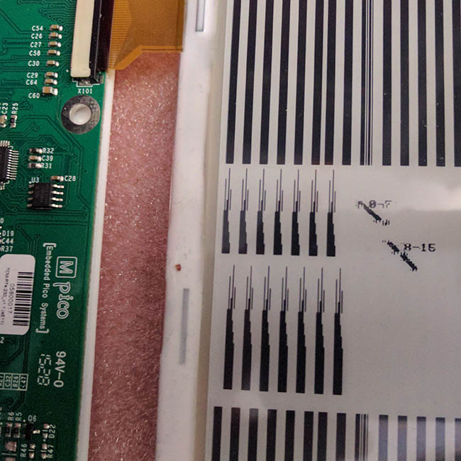
I gave up using PHP for this. As I had the working Java snippet, I made a quick command line Java application that accepts a PNG and converts it into an EPD. Learning to make my first Java application was less infuriating than getting this working in PHP. I since had someone who understands Java look at my creation and confirm that it is not terrible.
This makes the process a little more chaotic than I would have liked: A cron job triggers a bash script every ten minutes and runs task.php in PHP CLI. If something has changed, PHP saves a new PNG and executes another bash script (>.<) that runs that PNG through my Java application and then transfers it to the frame. Once the screen has processed the image, after about twenty seconds, it updates. It’s possible to force it to update quicker by mounting and unmounting the device but I’m not in a hurry.
My plan is to release all the plans and all the software on my GitHub account once it’s usable.
Experience and re-printing
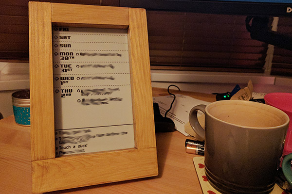
I’ve had the frame on my desk for a few months now and I’m delighted that it’s actually useful. I refer to it all the time. I’m embarrassingly proud that I made a thing that actually works. I make it to most meetings on time now!
I had some early issues with timezones (leading to me gatecrashing several meetings) due to Google’s .ics file being difficult to interpret. If my manager in Greece invited me to a meeting, the calendar event would be set for his timezone. I had made an attempt at converting these myself but timezones are hard and daylight savings set it all on fire. To get around this, and improve support for repeating and cancelled events, I switched to using Google’s API. Getting OAuth up and running took a little while but after that it was easy to replace the function that pulled from the .ics address with one that used their API. Now Google handles all those horrible timezones and recurring events.
There were also some issues with the frame’s design that I kept wanting to address. I was unhappy with how deep the bezel was, it’s 15mm and that creates a lot of shadow on a screen that is already hard to see in low light. It’s also spectacularly ugly.
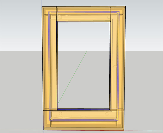
I enjoyed 3D printing the board to hold all the circuitry and in the process had measured all the parts reasonably accurately. I decided to 3D print a new frame. I used SketchUp again and eventually discovered how to make a rounded box.
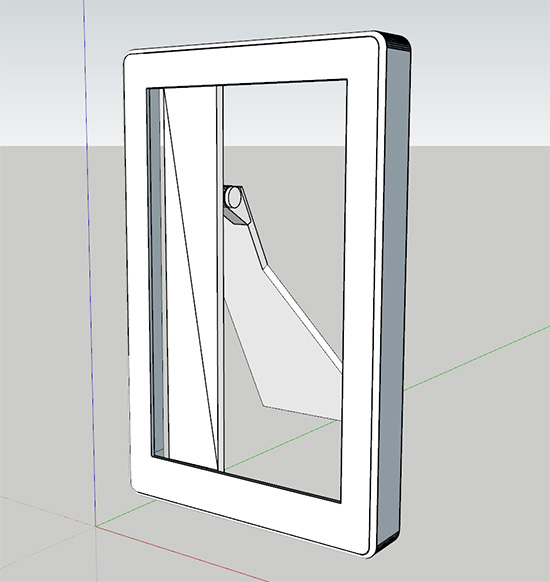
It’s considerably more svelte than the wooden design. Here’s the two overlayed and made transparent:
The design is made of 11 parts which will hopefully slot into each other. Also, despite no knowledge of what I’m doing, I am 3D printing a hinge!
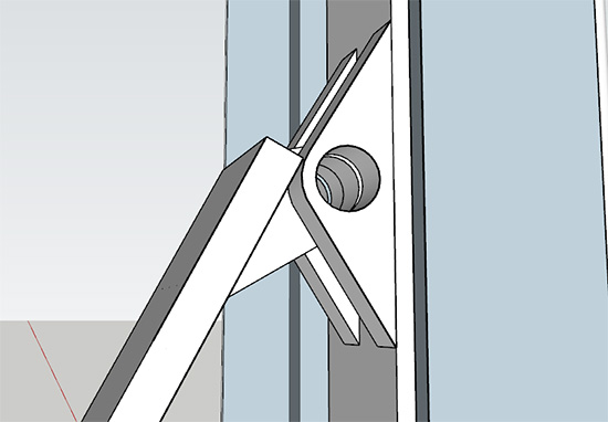
I’m having a little rod with a cap printed too which will slot into this but, as that’s the part I’m least confident about, it will also take an M6 bolt. Rather than attempting to design something stiff, I’ve opted for loose and flappy and have designed holes on the kickstand and main body of the frame that a string will connect between. This will keep the frame upright.
The number of parts grew and grew as I realised how most of the objects I originally designed could not be printed. The main body is now in two pieces as it requires holes and cut-outs on the back but also has a tapered front bezel. I’ll be using lovely metal 5mm insert nuts sunk into the model to attach the board with the circuitry. To save re-printing that board, I used the measurements from it. The source of those measurements are my uncalculated and imprecise bodgings on the very first cardboard attempt. This means they are not very neat.
I’m using 3DPRINTUK again and have opted for their dyed “Carbon black” PA2200 nylon. I’ve also asked them to polish it. I think this will look wonderful against the light-grey and black colours of the e-ink screen.
Final assembly
This post continues the story about my e-ink calendar frame and concludes the rebuilding. This time I actually remembered to take some nice photographs!
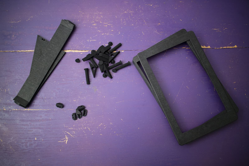
I dashed to the post office to pick up the finished models only to find that they hadn’t been dyed black; they were still white. I did consider working with them but they had dyed some of the smaller parts, so that would have been weird. 3DPRINTUK quickly sorted that out and a few days later I had them back in my hands and in the correct colour.
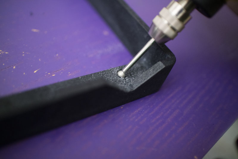
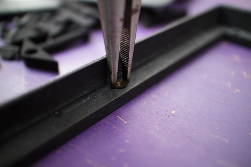
I designed the holes for the screw inserts to be as tight as possible and they ended up being a little too tight. This is still better than them being too big as I could just use a Dremel to widen them slightly and then set to work.
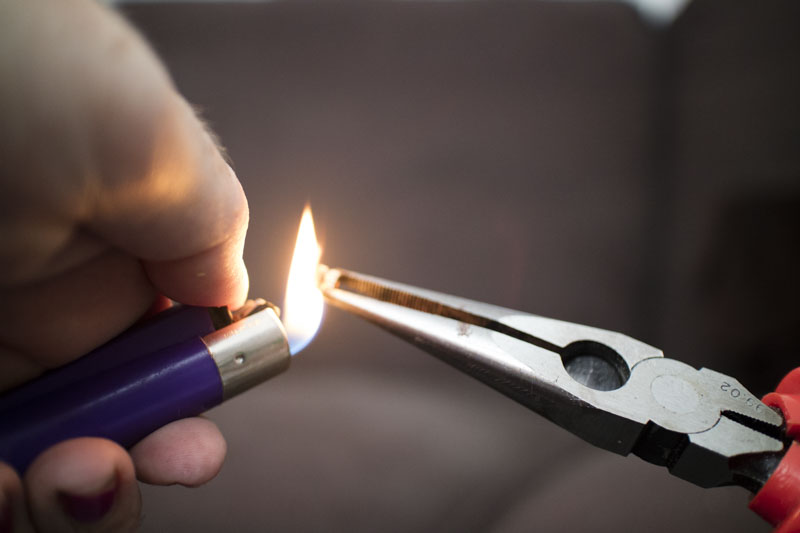
Heating the inserts with a lighter let them melt into the plastic as I pushed them in. This set them enough that I could tighten a screw without them working their way out.
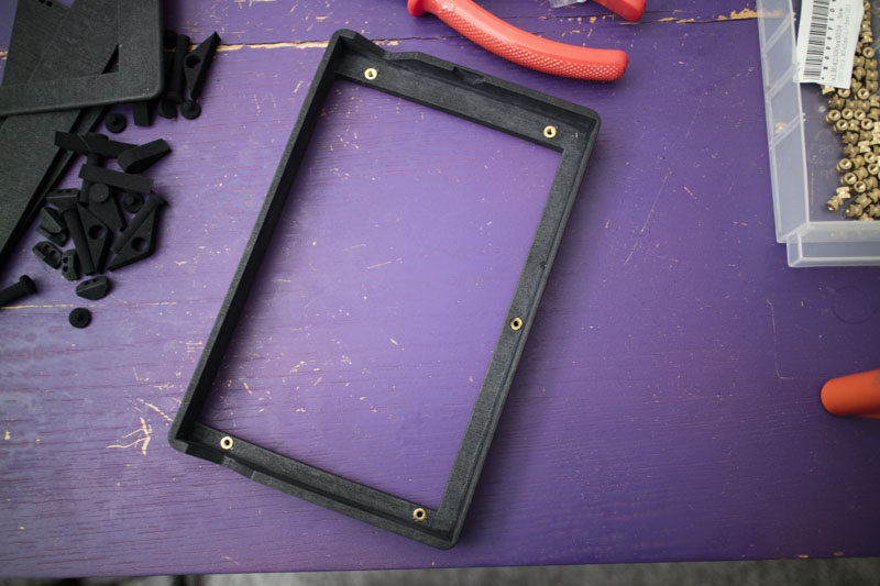
Next I attached the front. I had created this as a separate part to ensure it printed correctly. I’ve since learnt that 3DPRINTUK’s magical SLS machine made this unnecessary but it gave me something to build. That was fun.
This lined up perfectly and looks like one solid object. The screen and circuit board dropped in neatly and the screws lined up. I was a little terrified of that part.

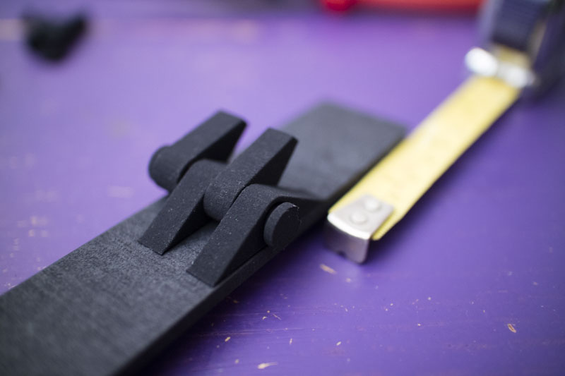
I had a little issue with the back panel: while everything fitted together perfectly without a circuit board and screws, I didn’t account for the height of the screwhead and needed to hack away at that part. It’s not externally visible but I’m sad knowing it’s there. My hinge assembly worked really well, I was really happy with that.
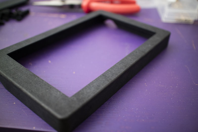
With the high-tech fastener secured (I tied the string on), it was all set. It booted up without any complaints and, I think, looks great. The matte black frame, grey background to the screen, and black text look wonderful together. I was able to increase the size of the aperture so much that I gained some precious pixels back!
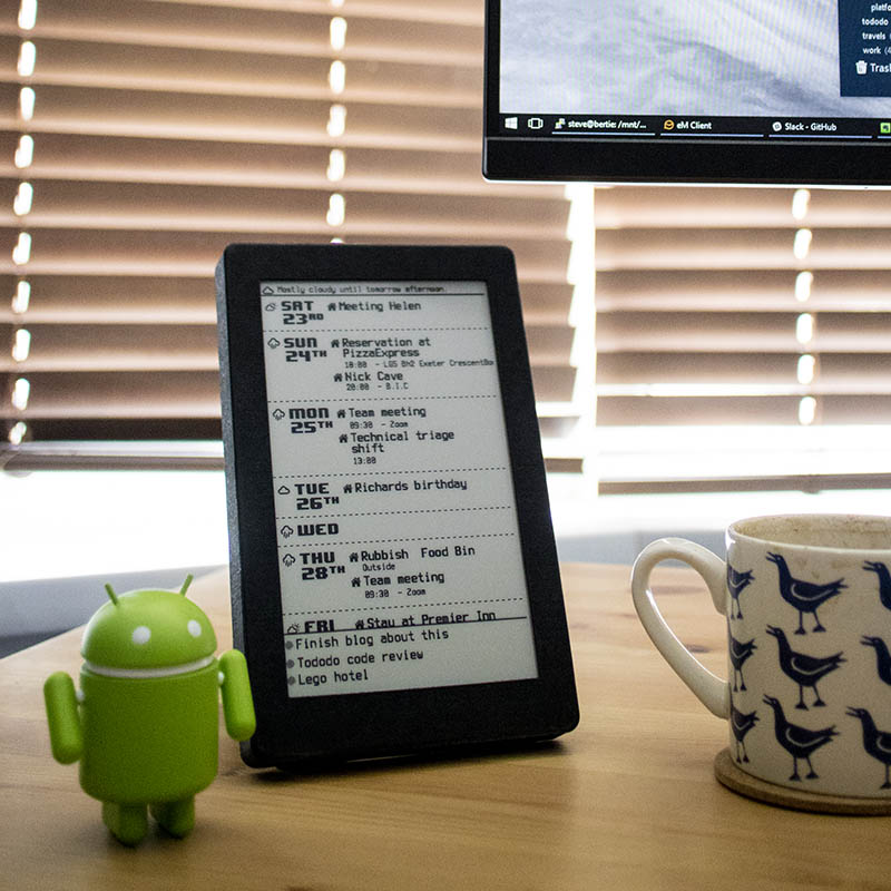
There we go! :3